
Isobaric Console Pics and Tutorial
Good evening peeps!
As promised, here is the thread regarding the console in the Big Meat and it's construction and design. Since there are so many of you who want info, i shall share , cuz I really am an all-around nice guy
An Isobaric box is an enclosure where two woofers are mounted face-to-face and wired out of phase with each other, like a push/pull fashion. This design's purpose is to REDUCE box size requirements and ENHANCE low end extension. In comparison to a standard two-sub sealed enclosure, vs. an isobaric "pair" of subs , there are several notable differences>>>
1- the standard box will be, for example, 2 cubic feet internal volume, let's say each sub needs 1 cubic foot of air space NET. The Isobaric mounting of the same two drivers would require exactly 1/2 of the airspace normally required for a SINGLE woofer! Thats right folks...these same woofers if mounted isobaric, would only need 0.5 cube NET of enclosure volume! A DEfinite space saver.
2- the standard box will have an effective cone area of the sum of the area of both drivers. The Isobaric box will only have the effective cone area of a single driver....advantage in overall output, standard box.
3- the isobaric box will not be as loud as the standard box overall, but will exhibit louder levels of output as the frequency drops. More on this in a minute, but deep bass output will give the slight advantage to the isobaric box compared to the standard box, given the same input.
4- Since the isobaric box will have the outer driver in "magnet-out" fashion, there IS a chance that motor noise will be heard inside the vehicle, esp if the enclosure is inside your listening environment. Not all subs will exhibit this, but some can and do and it IS audible. Advantage if not "handled" peroperly, standard box.
OK, so how exactly does an Iso box work? When you take a pair of drivers and mount them in this fashion, you effectively double the moving mass of a singular speaker, double the motor structure of a single speaker, and double the power handling of a single speaker. An Iso config actually "traps" a collumn of air between the cones and "push/pull"s this air mass along with the two cones themselves...follow me? This added weight actually helps to enhance the excursion capabilities of the driver in comparison to the same driver mounted normally. The Xmax that the single sub is able to achieve on its own with a given input CAN BE EXCEEDED MECHANICALLY with an isobaric pair of drivers given the same input, provided the woofers used are capable of additional excursion without the v.c. hitting the back plate. Still with me?
OK, so this phenomenon actually changes the woofers Fs to a LOWER value and helps extend low frequency response compared to a standard enclosure. Awesome, right! Well, there is a tradeoff. Since the moving mass is actually more than the weight of the two cones, the motors can't quite "drive" the subs with exactly the same force, so you give up a slight bit of efficiency. Furthermore, this additional mass ADVERSELY affects the transient response of the subs as the frequency rises, becoming very noticeable above 80Hz. THis means the Iso pair actually begins to sound muddy with decreased resolution if played at a high enough frequency. Midbass output and clarity winner will DEFINITELY be the standard box. Think of it this way, the added mass is harder for the motors to control during transients...make sense?
In the BigMeat, I use 63Hz as my Sub to front stage x/o point, and have ZERO problems with transient resolution using the GTi subs. The GTi's work great for this app due to very large physical excursion capability, strong motors, and lighter-than-most-but-still-very-strong paper/pulp cones. They called for 1 cube NET sealed per driver. That would be two cubes PLUS driver displacement PLUS adequate baffle area for the subs to mount and play from. Since there is no way I am gonna build a console with two subs on top firing up, my design/space was ecedingly limited. Two cubes NET doesnt seem like much, but it would be 2.5 total internal after bracing and sub displacement! And thats damn big to be cramming between the seats!
So, the dilemma was A)space B) mounting "baffle" the bass would play from C) concealment D) retain factory armrest.
I pondered and pondered, and since I AM Fasha and I have been around since sliced bread was invented, I called upon my Isobaric knowledge to help a brotha out
OK, to continue, I had 4 major dilemmas working against me when designing the enclosure. More like "stipulations" in a sense I guess....I wanted>
#1 to have at least the cone area of a single 10 playing subbass for SQ judging
#2 to build an enclosure that would play to 20 Hz for same reason
#3 vent the output of the enclosure forward toward the dash
#4 still keep the factory arm rest AND the factory cupholders and 12vdc outlet up front.
Additional considerations were the final ohm load of the enclosure. In my case, I chose the JBL PX 600.2 to run the sq subwoofer(s) as the best amp to use from JBL. Why, you ask? Well, not to get off track, but good quality class AB amps are the best possible amps for driving an audiophile-grade subwoofer due to low distortion, good damping, decent efficiency, good dynamics-control-and frequency resolution. I personally would never use a ClassD on subs (thats what the BPX amps are) for SQ due to higher distortion and less control /frequency resolution. Sure they are more efficient, but at the cost of pure audiophile performance. Also, the BPX amps have a non-defeatable DBO circuit which is essentially a sub-sonic filter---again, totally not wanted for an SQ application, but perfect for SPL
Likewise, I'd never use a class A on subs unless I had the money and battery/power supply to burn, and the best A/C on the planet to quench the fire that would be brewing under the back seat due to INEFFICIENCY and the amount of heat generated. Totally useless technology when used on subwoofers imho. Mids and highs? Now that is a different story altogether
OK, back to the topic..Since the 600.2 is my sub amps of choice in this truck, let's look at the impedance requirements...4 ohm MONO minimum, 2 ohm stereo. Now let's look at the GTi subs, they are ONLY available in dual 6 ohm coils! Well, wtf JBL? I cant use a single GTi 10 b/c the amp wont run 3 ohms mono with the coils wired parallel...well , it WOULD but it would run hotter than necessary, THD would increase, damping factor would decrease, and blahblahblah. Definitely NOT the situation I personally want. At the same time, if I wired the sub coils in series, then I have a 12 ohm load in MONO, whick is 3 times more resistance than a standard 4 ohm driver, and sub output would suffer due to "choking the wattage" out of the amp. Again, NOT the situation I want at all.
Well, what If I used TWO gti 10's, then my ohm load would be 3 ohms stereo or 6 ohms mono, definitely a great load for this particular amp. And since I am a big proponent of running subwoofers in MONO whenever possible, esp if in the same box, the 6 ohm MONO choice was Ideal for me. Not to mention another important factor....at higher resistances, class AB amps actually have BETTER damping /control over the subs, and LESS THD, as these factors always get better as ohm load is increased, worse when it is decreased. So, It's settled! I need to run TWO subs, not one, with this set-up and product line I am using
But holy crap! THats a big box for two drivers! GTi 10 displacement is .108 ft3 each and they each need 1 cube NET sealed airspace. Aperiodic venting thru the floor was an option, but I decided against it due to timeframe constraints and mounting options...more on that in a minute. So, at the very least, my enclosure for two subs was going to be 2.216 cubic feet plus wall thickness, given 3/4" walls minimum, and I am over 2.45 cubes total outside dimension! TOO BIG!
Let's take this a bit further..as I pose the question "How would the two subs mount?" It should be obvious to you all the there is no way to mount two GTi 10s in "cone-out" fashion where they are both firing forward from a space that is 12" wide! It is just not possible unless you go vertical, but who wants a tan 24" tall refrigerator-looking thing between the seats of their truck!?!No one does. Well, we could mount the subs firing up, one behind the other, right? Well, then the output would not be directed forward, we'd have to make a durable grill to protect the subs, and they'd be so close to you with two point sources that all sorts of sonic problems would occur>
First off, there would be nothing for the subs to "load" off of, meaning they'd be firing into open air. THis was NOT an option in the Meat b/c we already were going to mount the subs closer to the listeners than a normal install, and since we all know that the lower the frequency, the longer the distance it takes for the sound wave to develop, thus if we DID mount them firing up, we'd have virtually NO deep bass output in the listening position because the subs are simply too f-n close to you for the wave to develop. We'd have SUPERB tactile midbass, but we would localize it as coming from this "hump" between the seats---NOT good. We wouldnt realize decent low bass from this type of box until we walked infront of or behind the truck as the added distance from the enclosure would allow for a near-complete soundwave formation. OK, you say, we get it! Enough about mounting them facing up, that wont work in SQ.
But what about mounting one firing forward and one firing backward?? Well, that would direct the output away from the listeners and give the wave additional time/distance to develop for the lower frequencies, but this poses a different type of problem----Multiple point-sources playing the same frequencies. In the Big Meat, If I built the console this way, the rear 10 would be closer to my ears than the front 10, so I'd get a sort of "out-of-phase" area in the middle of the truck where the bass would seem to come from. If I had the capability of time-alignment for EACH DRIVER, I could probably band-aid the situation and correct for arrival times, then my sub bass performance would be dependant on achievable wave development, whatever "loading" the cones were able to get off the dash and rear seat, and how well I could make this point-source sitting next to me move forward and blend with the stage. BUT WAIT! I have only a single MONO output of the DEQ to work with! FURTHERMORE, I already decided to run the pair of drivers in MONO, NOT stereo! So I can not correct for this type of box design correctly, and I know it will not sound correct, so Ix-Nay on the one front-one back idea.
Ix-nay also on the "fire both subs downward" idea because now, I would need an additional 2-3" of clearance UNDER the box for the woofers to fire properly, making the enclosure over 3 cubic feet total! WAY TOO BIG! Sure, this would be great for deep bass reinforcement due to the subs being able to "load" off the floor and adding distance from drivers to ear for more deep bass soundwave maturity. But I'd still prefer a singular point source anyways. MAN! I wish at this point that JBL had simply offered the GTi in a single 4 ohm or dual 2ohm config! Life would be so much simpler, wouldnt it
What to do, what to do...
Once I have made it this far in calculating and contemplating the console, I am sure that during one of my many day-dream sessions that take place in my head about car audio, I remembered the Isobaric design. Could this be my saving grace? Is it possible to address all of my issues and demands for the sub enclosure given my criteria?
THe answer, my good friends, is an emphatic YES!
Stop the presses! I'll continue in a moment
PArt 3>>>
So, an Isobaric configuration seemed like it would work because it would allow me to run the pair of drivers(stipulation) in mono (another stipulation) and the only sealed airspace I'd need would be .608 ft3 total (yet another stipulation). There are two main types of Isobaric boxes. THe first is refered to as the "clamshell", the second a "linear array". The standard isobaric design is where the drivers are loaded Face-to-face and wired out of phase so they "push-pull" together as one unit (the clamshell),,,,OR,,, they are mounted "magnet to cone" in which they are arranged in line with one driver directly in front of the other driver and the two are coupled together with a fixed airspace such as a cylinder between the two (this is the "linear array"). Anybody remember the Blues drivers that were iso pairs mounted in a clear acrylic tube magnet-to-cone for free-air and sealed application???? I always thought they were cool
Anyways, the linear-array would have the woofers wired in phase with each other, and the air space between the two cones became the "coupled" collumn of air, the same as the airspace sandwiched between the cones of the clamshell is the air collumn. GOt it? good.
A variant of this classical Isobaric design is called Iso-planar. This box works on the same principle as the clamshell design, but instead of face-to-face mounting, you mount the subs on the same baffle and create a very small coupling chamber above them so that the cones will work in unison when wired push-pull. Behind the subs, you would have the sealed chamber behind one driver, and vent the other driver somehow into the listening area.
Just imagine a clamshell config, now open the clam up facing both halves upward, and create a sealed chamber above them as if they were never split. Got it? good
The air collumn trapped inside this small sealed coupling chamber adds to the masses of the cones themselves, yet the actual cone area playing into the listening environment is still only a single 10 cone and a singular point source, just like a standard isobaric box
So how does this pertain to Bigmeat? Well, I weighed the options against one another like this.
CLAMSHELL---no other way but to have sealed box on back of console, outer driver playing facing forward, subs face to face on their side with magnets pointing toward front and back of truck. I would get the forward firing I wanted, but no down-throw loading of any kind. The only way to make a viewing window for the drivers would be to show a single chamber, OR , somehow have the baffle dividing the two chambers and subs "pretty" so it can be seen in either the sealed or the output chamber. Hmmm, not to crazy about that. Might look kinda "rough under the edges" if ya know what I mean, and time is an issue.
LINEAR ARRAY--- only option is mounting the same way, but this time there are two sealed chambers, one behind woofer 2, and one between the woofers coupling them together. THe net box length would end up being the same as the clamsell, and the advantage to this design is there would be no motor noise b/c a cone was firing into the listening environment, NOT a magnet like the clamshell. Plus I could put a single plexi window in the middle chamber and see the iso array of the cone of sub #2 and the magnet structure of sub #1...pretty cool. But was there something else I could do to enhance the low bass performance? I mean, this is effectively only a single 10" driver, right?
ISOPLANAR--- this design could keep height of the console to a minimum since the drivers' mounting depth is about 1" less than the overall basket width. OK, but I'd still need the back sub in a sealed chamber, the front sub venting forward, and a coupling chamber just like the linear array. Well, why not kill two birds with one stone and make the wall of the coupling chamber PLEXIGLASS so we can show off BOTH woofers at the same time!?! COOL! But wait, the sub that plays out of the enclosure would be magnet out, and possibly have motor noise. Well, that is true, but as you will see in the pics, the magnet-out sub isnt "hanging out" into the listening area...it is inside a chamber that has a vent that faces forward. And speaking of the orientation of the outer subwoofer, this isoplanar would allow the output to "downthrow" toward the floor, further enhancing low octave performance-SWEET! Also, if I was to make the front vent area into a 'chamber", I could limit the area of the opening of the chamber and in essence make a "slot-load" at the same time to mildly increase the efficiency. NUTRASWEET!
As you will see in the pics and documentary to follow, this box design proved to be a perfect fit into the space provided, allowing full use of front cupholders and armrest with only adding 2 " of overall height to the armrest, and met all of my audiophile-based criteria at the same time. I am totally and utterly happy with this enclosure and it performs beautifully. PLUS I get to enjoy the added "solid surface" to set stuff on, etc etc
Stay tuned, pics are time consuming.

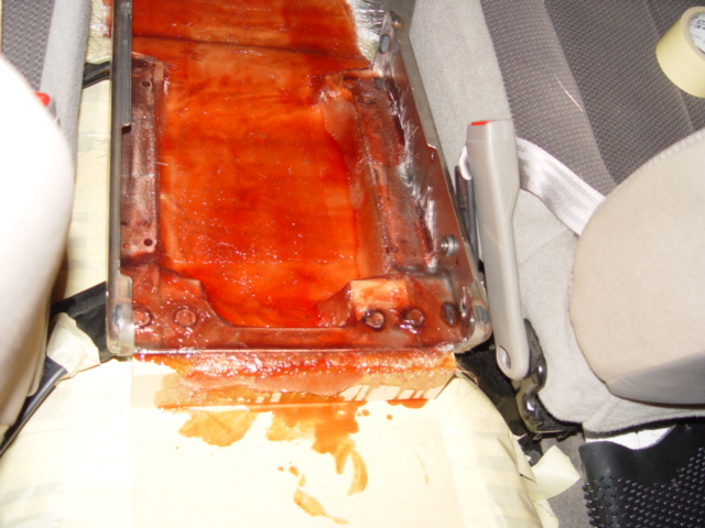
Thats the bottom of the center seat after removal from the truck as I begin removing the storage compartment and upholstery.
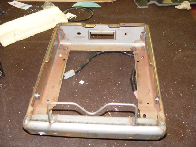
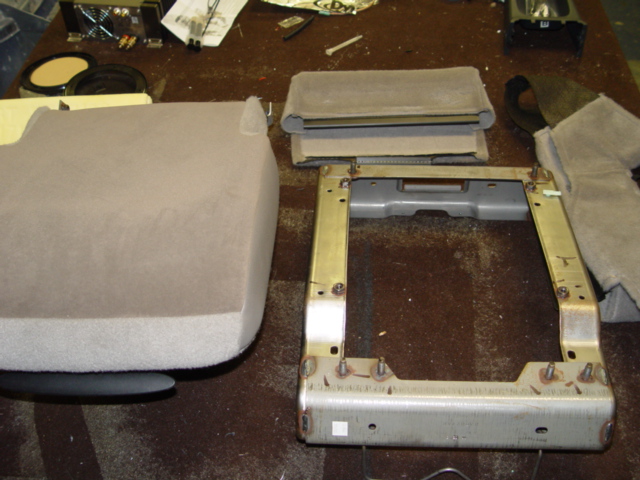

There are a few shots of the steel frame that bolt into the truck with 6 12mm nuts and studs securing the entire center seat section to the frames of both the driver and passenger seats. Also seen are the studs that are welded into this frame from Dodge...they are pretty damned meaty.
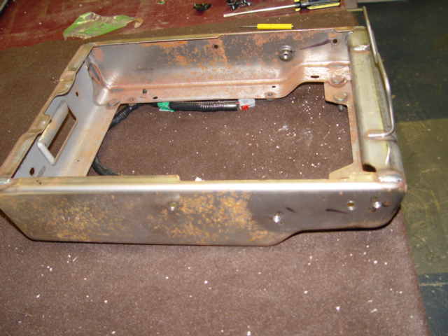
Now, here's a shot of the frame before cutting, flipped upside down.
and then after some trimming (remember, it aint an install unless the airsaw was involved LOL! :P )
The next two shots will show that I cut out enough material so that a flat piece of MDF could be secured to the frame and used as enclosure sides within this frame.


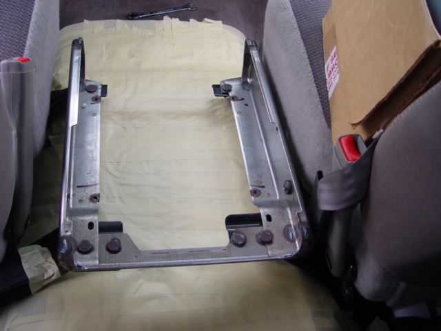
Next, I tape off the entire area inside the truck with masking tape in preparation for what helped make me a legend in my own mind, my friend, Mr. Fiberglass. LOL!.


After masking, my modded console frame is bolted back into place between the seats. Please note, this frame actually mounts so that it is 1.5" above the floor. Since height is an issue using subs that are 10: deep, I am going to use 'glass to extend the bottom of said enclosure all the way down to the floor level for added clearance.

OK, so I also need to extend this console a little bit more both in front of AND behind the frame to make the best use of space and keep height to a bare minimum. In the front, I simply extend my 'glass floor mold. In the back, I attatched a couple pieces of 3/4" MDF to the steel frame and 'glassed them in. THey simply sit flat on the floor.

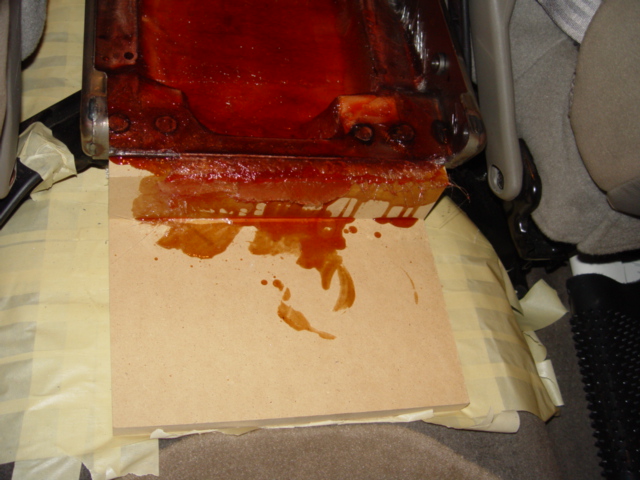
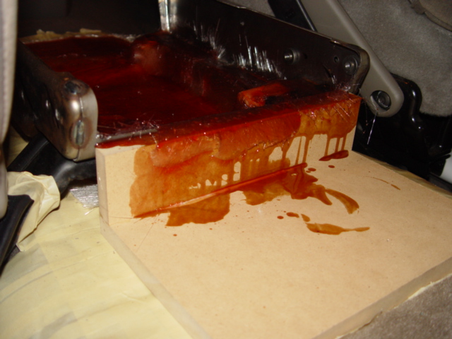
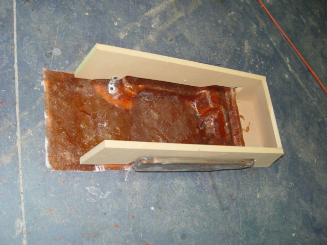
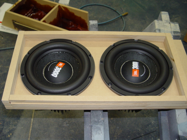
Notice I actually 'glassed this base mold right to the steel frame (after scuffing the steel, of course). THis is how the basic "bottom" and "mounting points" of the console were made. I then took the mold out, trimmed all the rough edges, and placed the subs in to check clearances and whatnot.

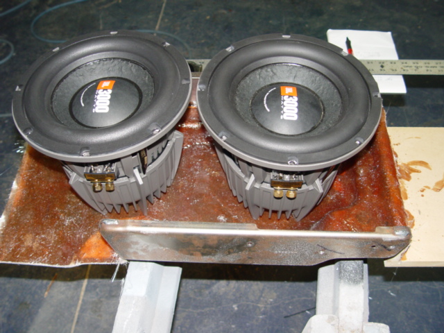

Did you notice that in order to keep the overall enclosure height to a bare minimum, the rear woofer had to be placed just in front of the rear frame bar, where my new 'glass mold "dropped down" to the floor??? This mandated that the two drivers could only be moved back to that point at most...boy I sure hope there is enough front clearance for my cupholders and all that to still function
OK, so next up, after measuring the subwoofer mounting depth, sealed chamber dimensions and necessary enclosure angle for .6 cube NET volume given my console "width", I cut the sides and back of the enclosure from 3/4" MDF, secured them together, then screwed them into place to the frame.
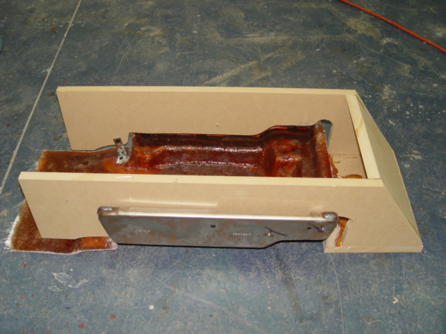


Did you notice above the shape I had to cut the MDF sides so that it form-fit closely to the frame and bottom? Also notice how the sides fit together with the wood part of the bottom at the back of the enclosure.
Next, here's a shot if the bottom after a good trimming.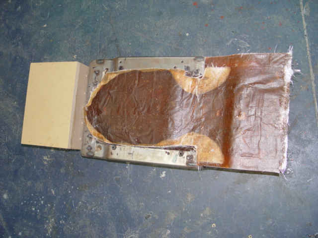
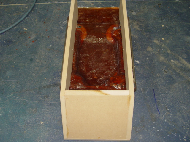
OK, so the next step I took was make the baffle and the sides of the "coupling chamber". YES the baffle is 1.5" thick, and I used a border of 2 layers more of MDF to greate 1.5" high "walls" around the woofers.
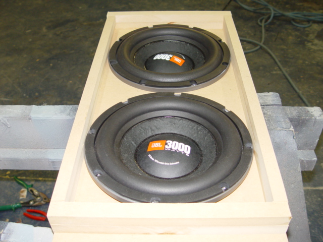

Not much clearance around those woofers, eh Clarence? YOu are right. In Isobaric boxes, it is best to keep the coupled air chamber to the smallest possible size as the more air is in there, the more it's compliance will work against your subs operating as a single unit. THings will get sloppy. But, making this area so small is exactly a good thing in this console, b/c I am trying to make the enclosure, limited by the location of the subs, fit with enough clearance to still use the cupholders and whatnot. Worked out good.
Next, it is time to bond the wood to the steel and make the enclosure THICK and sealed! THis called for Bondo and fiberglass, and lots of it! I just had to keep in mind that the steel had to remain "uncovered" on the sides for reattatchment of the armrest. No problem! We will seal from the INSIDE


That was several layers of 'glass laid from base mold, across the steel, and onto the MDF sides. I also laid down additional layers to the bottom of the sealed chamber to stiffen the base mold itself. OH, and did you notice, the divider placed between the woofers to create the rear SEALED chamber for sub #2 to sit in???? It to was glued, screwed, and 'glassed in place
Next, the speaker wires were run into the box from the side just under the steel frame. I also trimmed out the front "vented" area along the bottom so the sub could play into the carpet somewhat, but yet the sides of the enclosure still rested flat on the floor, preventing bass from playing anywhere but forward.

I then used screw down ties and silicone to seal the wire in. I also began using Dynamat xtreme INSIDE the box. I want this thing to be as heavy and as acoustically "dead" as possible...and it is.
Acoustic egg-crate panels, De-flex pads, and more dynamat in the sealed chamber

Damn thats a deep driver! Sheesh! No wonder keeping height to a bare minimum was important 
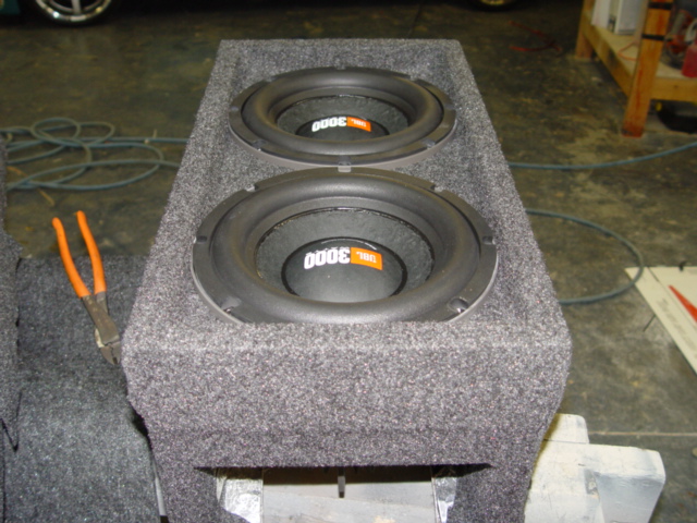
Heres an overall shot of the subs sitting in the enclosure after I covered the entire beast with trunkliner.

I guess I dont have a pic of the baffle being screwed into place, but it was done in standard fashion with 3" screws and woodglue. Then I glued and nailed each layer of the coupling chamber strips into place, siliconed them in, and then carpetted. Moving on...
here is a shot of the opening that the enclosure plays out of. Notice I dampened the piss outta this chamber too, and instead of making a big gaping hole (like bob's mom) j/k! , I made a smaller semi-slot opening which basically forces all output forward and downward, and makes it slightly more efficient than a wide open baffle. THis also helps to further add acoustic "travel time" to the journey to the listener's ears...SWEEEEEET.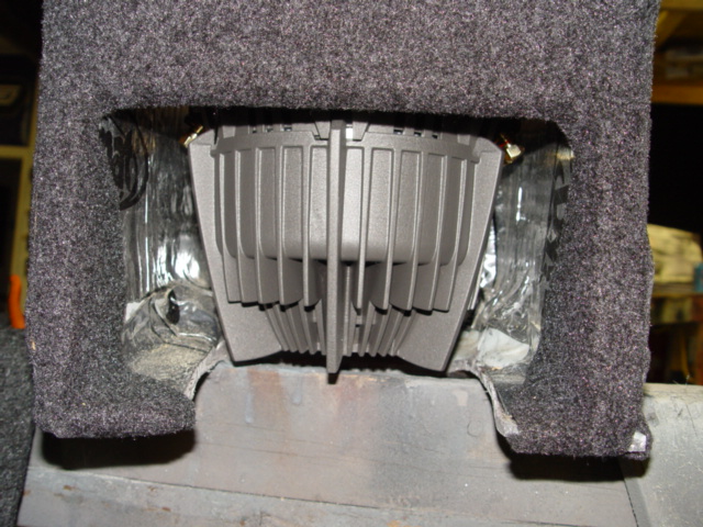
Next I cut a piece of 1/2" plexi to sit on top of the coupling chamber walls and secured it into place, thus sealing the drivers together! Also, we should note that, when wiring the two subs together, the 2nd sub was wired correct polarity, but the sub in front was wired in REVERSE POLARITY! Without doing this step properly, you are dead in the wata!
And I guess I should mention why if I am making this enclosure so damned heavy-duty did I only use 1/2" plex? Why not 3/4" or 1"??? THe answer has two parts, first, I have limited height to work with, so every little fraction of an inch is critical, and obviously 1/2" plex saves 1/4" of height. Secondly, the pressure inside the coupling chamber is miniscule when compare to an enclosure where the two woofers are NOT wired out of phase. The reason? Well, as one cone pushes, the other pulls equally, and the amount of air within the camber stays constant. Therefore the air inside simply "rushes back and forth" from one driver to the other. The woofers arent actually pulling and pushing against the plexi, they are doing so against themselves Get it? good.
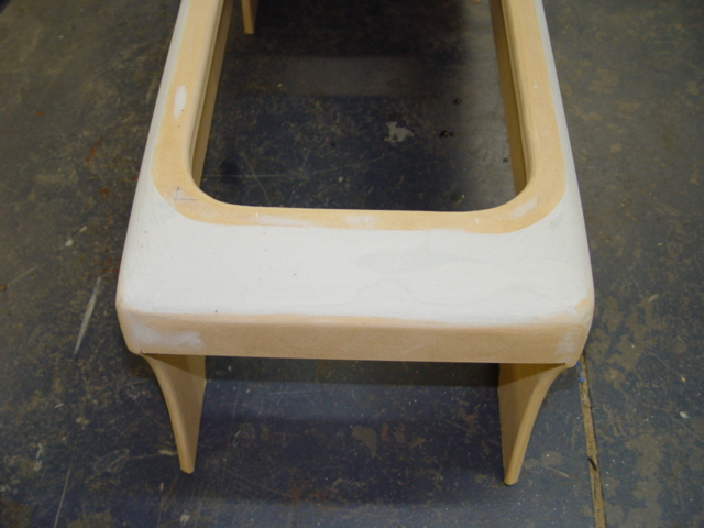
WHEW! THe enclosure itself is done woohoo! Now, we gotta make it look purty. I started by making a ring to sit on top of the plexi to serve as the view window, and cut a piece of masonite to fit over it as a cover.

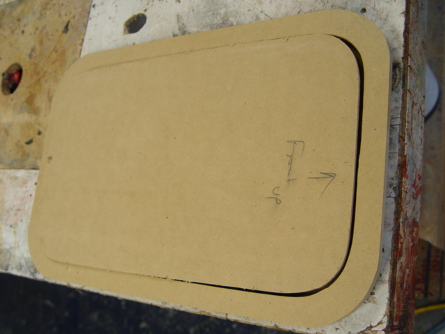
Then, I took this view window frame and cut out additional pieces that would come together to for a cover over the enclosure.

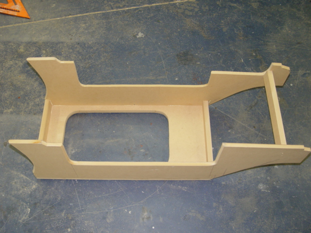


Added a drink holder mount
stretched some of my ghey-as-nutz fleece that I love so much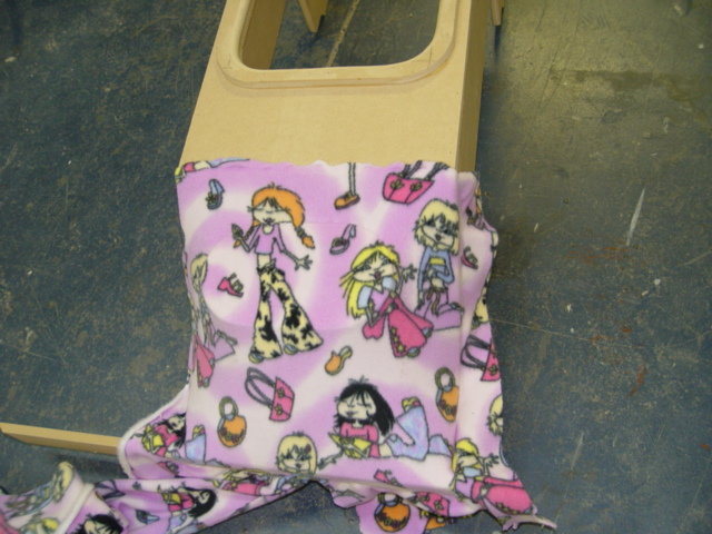
And glassed the back side to mold in the cupholders.
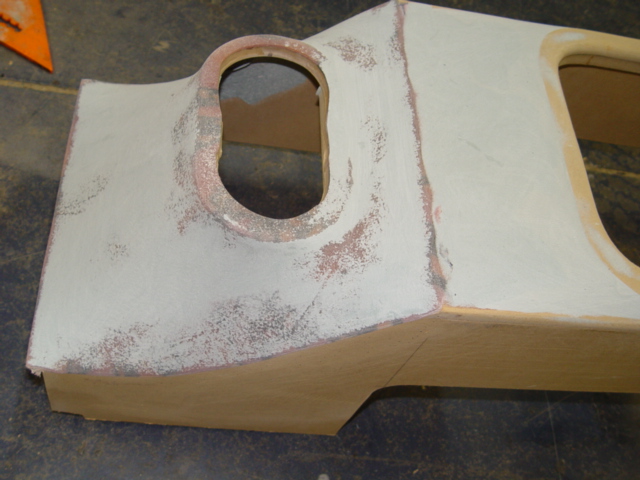
Next, I sanded, bondo'd, trimmed, and shaped this cover to get it ready for vinyl wrapping. Note the molded-in view window frame to give the top of the console a more rounded and custom look rather than a big sqaure.

Next, it is time to do another of my favorite things in custom car audio...WRAP VINYL! YEAH!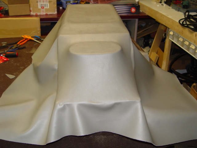

OK, so I bolt the enclosure in, which BTW, weighed in at no less than 110 lbs!!!, slide my new vinyl cover shroud over the enclosure, then bolt on the armrest (see pic below and you can see kinda on the side how all the pieces fit together. The lower carpet trim panel conceals wires going to amps and covers the transition from floor to enclosure for cosmetic purposes,,,it is just a piece of masonite on both sides.
NOW that that is done, let's discuss.
But first, let's talk about the claim that I didnt really gain anything in the space requirements category by going Iso rather than sealed.
As I mentioned earlier,for a standard box I'd need 2.5 cubes total external volume at MINIMUM just for the enclosure itself, and we still couldnt fire both drivers forward. Well, that is simply too big and would not have allowed all our SQ criteria to be met, nor could I continue to use front and rear cupholder...NO GOOD!
As it turns out, based on outside dimensions of my final enclosure shape, my Isoplanar box comes in at roughly 1.68 TOTAL outside dimension. It's not exactly 1/2 the space, but it is certainly a vast improvement over what was claimed that we'd only save maybe 1/3 the space, and it allowed for some nice shaping of the cover shroud and unobtrusive molding as well as meets all our sonic stipulations, and even enhances low bass performance!
FOr the Big Meat, this enclosure proved to be hands-down the BEST possible enclosure for SQ judging short of a dash rebuild. And boy howdy, does it look purty stealthy! Dont hate it, appreciate it LOL
there are many diff techniques that installer have come up with to make things like jigs, rings, inserts, etc. Winslow's method is one way, I have another way that involves making a "negative" of the shape you want to produce a "positive" duplicate, and other installers will undoubtedly have numerous other "tales of the router table".
HOWEVER, this particular window that I made, as well as the "insert" / cover was all done by a single cut out using a Bosch orbital jigsaw! Yes folks, my right hand + my Bosch = Steve, the human table saw and/or router table! LOL!
In all seriousness, I am able to cut such good lines with a jigsaw that making jigs and stuff with a router table is usually a waste of time. I do use jigs, speaker rings, and other various objects to draw and plot radiuses and shapes and whatnot, but unless I need to make multiple exact duplicates of a shape, I will almost always just use the jigsaw and get 'er done.
In this particular instance, if you notice on this pic>
> I drilled a pilot hole just to the INSIDE of my window outline, and made a single pass with the jigsaw...thus the jigsaw blade itself made a wide enough gad to allow for vinyl clearance and keep a tight fit
I then filled the pilot hole in with bondo, and used the router table to round-over the outer edges of the perimeter of said window>
>and then you can see the piece of 1/8" masonite temorarily tacked to the top (in the pic, its the bottom) of the ring to flush-trim and round-over that piece too, then I pried them apart and the ring went to join the other pieces to form the sub enclosure shroud.
THe masonite and the INSIDE window cut out would become my removable "exact-fit" window cover. I wrapped the masonite in vinyl, then the underside of the cutout in trunk liner, then bonded the two together with silicone. Worked like a champ!!!
But, I should mention that I put a 45deg router to the bottom edge of the window cutout insert before wrapping with trunk liner, just to allow additional clearance for the thickness of the trunkliner....remember, the jigsaw blade made the clearance for the vinyl on the window ring...but I still needed to allow clearance for the 'liner. Got it?
Look closely at the finished pix in the Big Meat Pix thread....do you see the cover over the sub window sitting there?
Well, it sits on top of the window. I needed a STIFF yet THIN wood product that I could use as a "top" to my removable window cover, as it would actually overhang the opening a bit to conceal any gaps and still look nice. THe Masonite IS that top piece that is warapped in vinyl. Get it now? It is only 1/8" thick, so it was a no-brainer to use for this purpose as it does not look out of place or tacky in any way.
Also, yeah Winslow hit the nail on the head...this enclosure is SOLIDLY mounted, dead as a coffin, and heavy as piss! THere is exceedingly minimal vibration from anything, zero noise, zero rattles, zero resonation. I cant stress enough that if the enclosure is near the listener, dampening and resonance control as well as building the best most solid mounting system possible is one of many "keys".
THe front chamber does NOT need to be any size at all, in fact, the front sub could technically hang into open air if you wanted it to. THe reason I built the enclosure to extend completely around the front sub was a compound one---
remember what I said...make all the bass vent forward, add rigidity, add surface area to the floor-portion of the box to better couple with the truck, add acoustic distance from the sub to my ears, etc etc.
The top chamber should technically be as SMALL as possible so the subs dont get sloppy and air compliance ("springiness") becomes and issue. Like you mentioned, just large enough to clear the drivers and NOT affect excursion. That is the best bet!
© 2007 Audionizzle for Shizzle! All Rights Reserved. Site design and development by PyroPopTrt Designs.